Real time clocks are extremely important when designing embedded systems where accurate timekeeping is needed for daily operations, data logging, metering applications, automation systems, security devices, clocks and alarms. A microcontroller like ATmega16 does not have a dedicated real time clock built inside, so an external RTC chip such as the DS1307 is used. The DS1307 works on the I2C communication protocol and keeps track of seconds, minutes, hours, date, month, year and day of the week, even when the main power is removed because it uses a backup battery. When interfaced with an LCD display, it becomes a complete digital clock system that shows live time continuously. In this blog we will understand how the DS1307 works, learn its pin details, understand the I2C communication between DS1307 and ATmega16, write the C program to read time, and finally display the running time on a 16x2 LCD. The complete explanation is written in simple language with clear diagrams so a beginner can easily understand the overall working.
Introduction to DS1307 RTC
The DS1307 is a low-power, full binary-coded decimal real-time clock that provides details of time and calendar. It uses an external 32.768 kHz crystal oscillator to maintain timing accuracy. It operates on the I2C bus, which means only two wires (SCL and SDA) are required for communication with the microcontroller. A backup battery of 3V (like CR2032) ensures that clock timing continues even if the main supply is removed. The DS1307 contains internal registers for seconds, minutes, hours, day, date, month and year and each register stores data in BCD format.
Pin Description of DS1307 RTC
| Pin No. | Name | Description |
|---|---|---|
| 1 | X1 | Crystal oscillator input for 32.768 kHz crystal |
| 2 | X2 | Crystal oscillator output |
| 3 | VBAT | Backup battery input (3V lithium cell) |
| 4 | GND | Ground |
| 5 | SDA | I2C data line for read/write data |
| 6 | SCL | I2C clock line |
| 7 | SQW/OUT | Square wave output (1 Hz, 4 kHz, 8 kHz, 32 kHz) |
| 8 | VCC | Main 5V power supply |
Working Principle of DS1307 RTC
The 32.768 kHz crystal connected to pins X1 and X2 generates the base timing signal. Internally, DS1307 uses this signal to increment its time registers. The clock continues to run when powered from the battery even if the microcontroller is turned off. The DS1307 communicates using the I2C protocol, so the ATmega16 must act as a master and DS1307 acts as a slave at address 0x68. The microcontroller sends the register address through SDA and then reads the corresponding time value. Since the time values are stored in BCD format, the microcontroller converts them into normal decimal format before displaying on LCD.
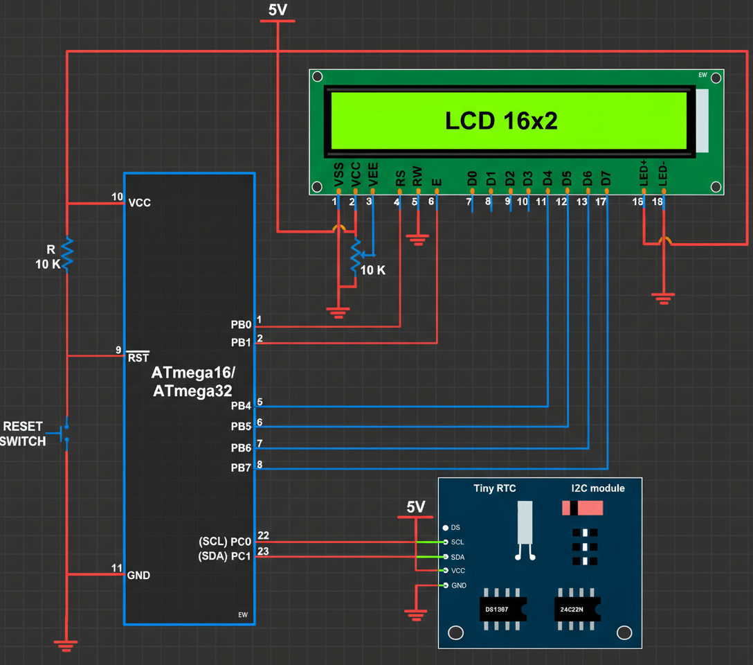
Block Diagram of ATmega16 – DS1307 – LCD
C Program to Read Time from DS1307 and Display on LCD
This program initializes I2C, reads the time registers from DS1307, converts the BCD values to decimal format and displays current time continuously on a 16x2 LCD connected to ATmega16.
#include <avr/io.h>
#include <util/delay.h>

#define DS1307_WRITE 0xD0
#define DS1307_READ  0xD1

void i2c_init() {
    TWSR = 0x00;
    TWBR = 32;
}

void i2c_start() {
    TWCR = (1<<TWINT) | (1<<TWSTA) | (1<<TWEN);
    while (!(TWCR & (1<<TWINT)));
}

void i2c_stop() {
    TWCR = (1<<TWINT) | (1<<TWEN) | (1<<TWSTO);
}

void i2c_write(unsigned char data) {
    TWCR = (1<<TWINT) | (1<<TWEN);
    TWDR = data;
    while (!(TWCR & (1<<TWINT)));
}

unsigned char i2c_read_ack() {
    TWCR = (1<<TWINT) | (1<<TWEN) | (1<<TWEA);
    while (!(TWCR & (1<<TWINT)));
    return TWDR;
}

unsigned char i2c_read_nack() {
    TWCR = (1<<TWINT) | (1<<TWEN);
    while (!(TWCR & (1<<TWINT)));
    return TWDR;
}

unsigned char bcd_to_decimal(unsigned char bcd) {
    return ((bcd >> 4) * 10) + (bcd & 0x0F);
}

void lcd_cmd(unsigned char c);
void lcd_data(unsigned char d);
void lcd_init();
void lcd_print(char *str);

int main() {
    unsigned char sec, min, hour;

    lcd_init();
    i2c_init();

    while (1) {
        i2c_start();
        i2c_write(DS1307_WRITE);
        i2c_write(0x00);
        i2c_start();
        i2c_write(DS1307_READ);

        sec  = bcd_to_decimal(i2c_read_ack());
        min  = bcd_to_decimal(i2c_read_ack());
        hour = bcd_to_decimal(i2c_read_nack());

        i2c_stop();

        lcd_cmd(0x80);
        lcd_data((hour/10)+'0');
        lcd_data((hour%10)+'0');
        lcd_data(':');
        lcd_data((min/10)+'0');
        lcd_data((min%10)+'0');
        lcd_data(':');
        lcd_data((sec/10)+'0');
        lcd_data((sec%10)+'0');

        _delay_ms(300);
    }
}
Applications of RTC Based Clock System
- Attendance systems
- Digital clocks
- Industrial time-based automation
- Data loggers
- Scheduling systems
Conclusion
Interfacing DS1307 with ATmega16 is one of the most important experiments because it teaches I2C communication, register access and real-time data management. The clock will continue tracking time even without the main supply, making it ideal for embedded clocks and long-term monitoring systems. With LCD output, the concept becomes visually clear and easy for beginners.
Comments
Post a Comment
Subscribe to Post Comments [Atom]